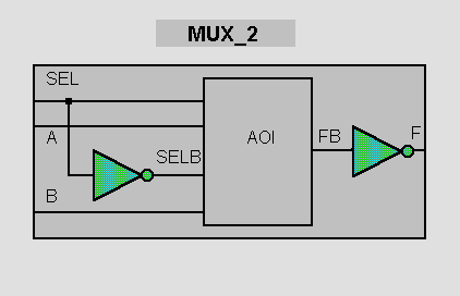
Modules can reference other modules to form a hierarchy. Here we see a 2:1 multiplexer with an inverting data path consisting of an AOI gate and a pair of inverters.

The MUX_2 module contains references to each of the lower level modules, and describes the interconnections between them. In Verilog jargon, a reference to a lower level module is called a module instance.
Each instance is an independent, concurrently active copy of a module. Each module instance consists of the name of the module being instanced (e.g. AOI or INV), an instance name (unique to that instance within the current module) and a port connection list.
The module port connections can be given in order (positional mapping), or the ports can be explicitly named as they are connected (named mapping). Named mapping is usually preferred for long connection lists as it makes errors less likely.
// Verilog code for 2-input multiplexer

module INV (A, F);   // An inverter
  input A;
  output F;

  assign F = ~A;
endmodule

module AOI (A, B, C, D, F);
  input A, B, C, D;
  output F;

  assign F = ~((A & B) | (C & D));

endmodule

module MUX2 (SEL, A, B, F);   // 2:1 multiplexer
  input SEL, A, B;
  output F;

  // wires SELB and FB are implicit

  // Module instances...

  INV G1 (SEL, SELB);
  AOI G2 (SELB, A, SEL, B, FB);
  INV G3 (.A(FB), .F(F));            // Named mapping
endmodule

// end of Verilog code
Yes, it’s time to dissect the code line by line again, but we’ll concentrate on the new lines as the module interface has been covered before (see A Simple Design).
// wires SELB and FB are implicit
The wires used in continuous assignments MUST be
declared. However, one-bit wires connecting component instances
together do not need to be declared. Such wires are regarded as implicit
wires. Note that implicit wires are only one bit wide, if a
connection between two components is a bus, you must declare the
bus as a wire.
AOI G2 (SELB, A, SEL, B, FB);
In a module instance, the ports defined in the
module interface are connected to wires in the instantiating
module through the use of port mapping. For thge instance of AOI,
the first wire in the port list is SELB. In the module header for
the AOI hgate, A is the first port in the port list, so SELB is
connected to A. The second port in the module header is B, the
second wire in the port list is A, thus the wire A in MUX2 is
connecyted to the port B of the AOI gate instance.
INV G3 (.A(FB), .F(F));
The second INV instance, G3, uses named mapping
rather than positiuonal mapping. In the port list for the GŁ
instance, the wire FB is connected to the input port, A, of the
INV instance. The period character is followed by the name of the
module header port; in brackets following the formal port, the
name of the wire is entered.
![]() Verilog
FAQ
Verilog
FAQ
![]() Doulos Training Courses
Doulos Training Courses
![]() Return to
Hardware Designers Guide Contents
Return to
Hardware Designers Guide Contents
Copyright 1995-1997 Doulos
This page was last updated 26th February 1997.
![]() We welcome your e-mail comments. Please contact us at: webmaster@doulos.co.uk
We welcome your e-mail comments. Please contact us at: webmaster@doulos.co.uk