Guide for Synopsys synthesis tool
Setup actions (only for the first use of the tool)
- Create some directory for the work with Synopsys (for example vlsiSynthesis) and go into this directory [>mkdir vlsiSynthesis] [>cd vlsiSynthesis];
- Copy into this directory Synopsys setup file for synthesis ~lrv/hdl/.synopsys_dc.setup [>cp ~lrv/hdl/.synopsys_dc.setup .]
- Inside vlsiSynthesis directory create subdirectory WORK.syn. Synopsys creates during work a lot of files, which is not needed to keep in vlsiSynthesis directory. [>mkdir WORK.syn];
- Invoke Synopsys always from the directory where the Synopsys setup file is (in this example it is vlsiSynthesis directory).
Invoking the Synopsys invironment
- Change directory to the directory with your synopsys setup file [>cd vlsiSynthesis];
- Invoke Synopsys with the following command: [>design_analyzer &] The following window will appear to you (Figure 1).
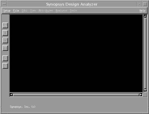
Figure 1 First window opening the Synopsys design analyzer
Synopsys converts the instructions in the dialog box into a sequence of “shell” commands. You can see the command by opening a Command Window (strongly recommended), to do this:
- Select Setup => Command Window
The basic steps required to synthesize a HDL design are the following:
- Selecting a target technology for synthesis (this is written in setup file);
- Reading in the HDL design;
- Synthesizing the design (optimizing the logic and mapping to the target technology);
- Writing out the synthesized netlist in a format, which can be used by gate-level simulation and/or FPGA layout tools.
Reading the input design
Execute the following steps to read in your design:
- Select File => Analyze…
- In the file browser select the file you wish to synthesize, for example counter.vhd. All files must analyze in dependence sequence (the top of design hierarchy is the last one). Choose the correct format of the file you want to synthesize and press OK. The Analyze File window is shown in Figure 2
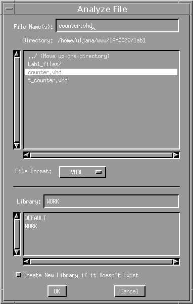
Figure 2 Analyze File window
- Afterwards you need to join all your modules. Select File => Elaborate…
- From the library either DEFAULT or WORK you should select the top module of the hierarchy. For example agener(one_direction).
- You need to specify the parameters of you design, if you have generic in your entity description. For example bitwidth=4;
- Press OK. The Elaborate Design window is shown in Figure 3
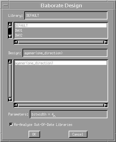
Figure 3 Elaborate Design window
Navigation in the hierarchy
- Double click on the icon representing your design. You will see a Symbol View showing the inputs and outputs of the design;
- Double click on the Symbol for the design. Synopsys will generate a schematic for the synthesized netlist;
- Icon “arrow up” will get you out from current view;
- Icons “hierarchy”, “schematic view”, ”netlist” are allowed to navigate among different views.
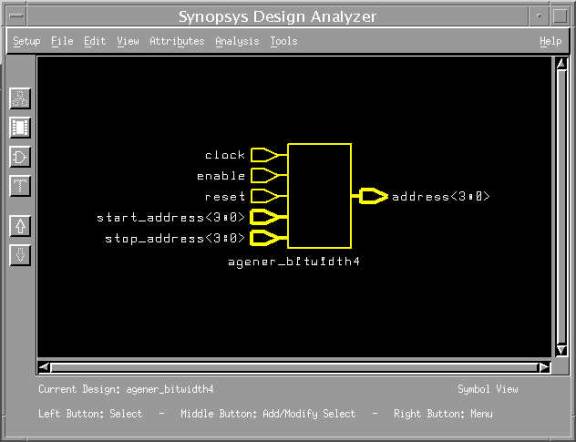
Figure 4 Schematic view of the counter design
Synthesizing the design
· Bind the clock signal with certain frequency. Select with left mouse click port corresponding to the clock signal (at schematic view of design). Select Attributes => Clock => Specify… Write the clock signal name and specify the period of the clock signal, for example 20 ns. Click apply button, then cancel button. (Figure 5)
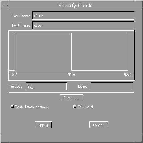
Figure 5 Speciry Clock window
· Optimize the design Tools => Design Optimization… Select “Map Effort” Medium and press OK.
· Look at the netlist view now.
Generating Reports
- In order to see the results of the analysis select Analysis => Reports… In the part of Analysis Report select Area and Timing. You can specify the output of the report either to the window or to the file. (in the lab’s report these results should be added). (Figure 6)
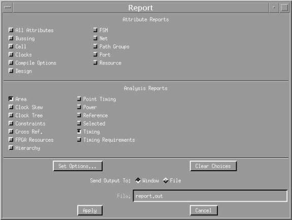
Figure 6 Report window
- Analyze the results
Exiting the synthesis tool
- File => Quit