Synopsys Simulation and Synthesis Tutorial
Account Setup & General Information
-
Copy the following files to your home directory:
-
Concatenate the following to your .bashrc file:
bashrc_update.txt
NOTE: If in you are setting a value for PATH in your .bashrc,
make sure you are doing so by using:
PATH=$PATH:(rest of yourpath here):.
-
The tools we will be using are part of the Synopsys package. All
of the tool we will be using are accessible only from the computer
named core.cs.ucr.edu. Therefore, in order to use these tools you
must logon to core using ssh (e.g., ssh -l yourlogin core.cs.ucr.edu).
- The following is a list of program that you will be using to
perform simulation and synthesis of your designs:
- vhdlan: syntax checking and design analysis
- vhdldbx: simulator
- dc_shell: synthesis tool
Simulation
In order to ensure that we have designed a correct entity we will need
to test that our design works as specified. This is done through the
process of simulation. During simulation a testbench is used to test
that the design behvaes correctly by stimulating it with artificial
input and monitoring the output. If our designs works correctly we
will see the correct results at the output of the entity we are
testing. The following provides a step-by-step description on how to
simulate a design using a testbench. We provide an exmaple named
DECODE that we will walk through in our description.
-
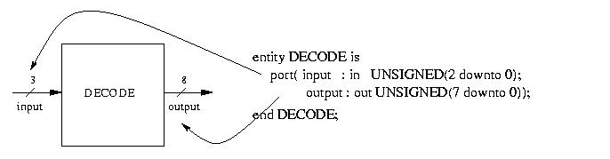
Design Entry: The first step in using VHDL for hardware design is
the design entry. This step can be accomplished using the text
editor of your choice. For our example simply download the file decode.vhd. This file contains a single
entity named DECODE which is a 3-to-8 decoder. Below is a picture
of the 3-to-8 decoder and its entity declaration. It
also illustrates how the port declarations correspond to the
inputs and outputs of the entity.
-
Work directory: All of the files needed to simulate you design
will kept in a direcotry named "work". Therefore, the first step
is to create a directory named "work".
-
Syntax checking: Use vhdlan to perform syntax checking and design
analysis. vhdlan should be invoked using the following command.
vhdlan decode.vhd
This file contains one small error that you should be able to
quickly correct. Make the correction and re-analyze the file.
-
Testbench creation: What is a testbench? A testbench is an entity
with no inputs or outputs that has a single instantiation of the
design under test (DUT) and a process or multiple processes that
will control the inputs of the DUT and verify it works correctly
by analyzing its outputs. The image below shows the simple
testbench entity used for testing the DECODE example.
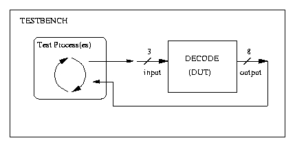
A testbench should be robust such that it
provides a high level of confidence that the design being tested works
correctly. There is more discussion on testbenches later in this
tutorial. For now, you can download a very simple testbench
decode_tb.vhd. You must also analyze
the testbench in order to simulate it.
One important aspect of any testbench is the configuration of the
testbench. In the file decode_tb.vhd,
at the end you will see the following code:
    configuration CFG_TB of DECODE_TB is
        for TB
        end for;
    end CFG_TB;
This configuration must be used in order to properly simulate our
design.
-
Simulation: We can now simulate our design in the following
manner:
- Run vhdldbx
NOTE: You will see many errors relating to key bindings. Simply
ignore these errors.
-
You must now choose the appropriate configuration of the testbench
you have created. For our example select CFG_TB. This will open
the Synopsys VHDL Debugger.
-
We now want to add the signals in our testbench and/or design that
need to be traced. So first we want to select "Hierarchy Browser"
from the "Misc" menu. This will open the VSS Hierarchy Browser.
-
You should see a green arrow pointing at the top level entity
you decided to simulate. Clicking next to this arrow will reveal
any components which comprise the entity. Select each signal that
you wish to trace and double-click on it. This will
bring up the Synopsys Waveform Viewer, and the bottom half of the
VHDL debugger will indicate that the signal is being traced.
NOTE: If the Waveform Viewer opens but no signals are present
then you should close the Waveform Viewer and retrace your
signals. Continue this procedure until your signals have been
traced successfully.
For our example open the entity named DECODE_TB and trace the
signals input and output.
-
We now want to simulate the design we enter the simulation
time in the VHDL Debugger and clicking on "Run".
NOTE: If you accidently click "Run" without entering a time, it
will run until you click on "Intr", which will stop it.
For our example, run the design for 100 ns.
-
We should see the correct simulation results in the Waveform
Viewer.
- If you wnat to see the input and output of the design in the
waveform, you must first add a cursor, by selecting "New at
Center" form the "Marker" menu in the Waveform Viewer. You can
also create a marker by typing Ctlr-m. Each marker can be moved by
dragging it to the desired location.
Good Testbench Construction
In order to test a design to ensure that it is working correctly a
"good" testbench should be constructed. However, what makes a
testbench "good"? The ideal testbench would provide an exhaustive test
of the design. In other words, it would test every possible
combination of input for every possible state of the design. It is
clear to see that this will become infeasible for anything but small
combinational designs. Therefore, the following is a list of
guidelines for creating testbenches.
- Asserts: assert statements ar an essentail part of any
testbench. They are used to test the value of a signal, port, or
variable against the desired value. In the testbench
decode_tb.vhd you will find the assert
statement:
assert (OUTPUT_O = 1 ) report "Error Case 0" severity error;
In this assert statement, the condition being tested is OUTPUT_O =
1. If this condition is not met, then the simulator will print
"Error Case 0". It will also halt simulation because the severity
specified was "error". If instead you wanted simulation to
continue, you can set the severity as "warning" which will report
the assert but continue with simulation.
-
Testcases: A testbench should test as many cases as possible in
order to create a high level of confidence. Thus, in a
combinational design, the upper and lower limits of the operations
should be test as well as many cases in the middle. Similarily,
in a FSM, we should ensure that all states of the design are
tested. we cannaot test all possible cases but, again, testing
boundary cases is imporant.
For example, consider a 4-bit adder. We should test the
boundaries of the adder, namely 0000 + 0000 and 1111 + 1111. We
should also test many values in the middle, such as 0001 + 1001,
0101 + 1010, etc.
Synthesis
Synthesis is the process of taking a design written in a high level
language, such as VHDL, and compiling it into a netlist of
interconnected gates which are selected form a user provided library
of various gates. The design outputted form synthesis will be a
gate-level design that can then be placed and routed onto various IC
technologies. The following provides all the steps needed to
synthesize a design and verify that the gate-level design works
correctly. We will once again be using the DECODE example and walk you
through all of the steps with explanations as to why each step is
important.
- All synthesis and synthesis realted operations will be
performed using Synopsys Design Compiler. To start Design compiler
run dc_shell.
- We now need to read in and analyze the design we wnat to
synthesize, for our example, we will enter the following command.
analyze -f vhdl decode.vhd
This will read in and analyze the design specified. The -f flag is
used to specify the format of the design be read, in this case
VHDL.
- Now, we will elaborate our design. Elaborate will
convert our design from the VHDL description into a Synopsys
specific format that is required for synthesis. This is done by
enterign the following command.
elaborate DECODE
NOTE: The design that you are elaborating is the name of the
entity of your design. This name is case sensistive.
- Now the fun part. At this point we are ready to actually
synthesize our design. The compile command will actually
synthesize our design into a gate-level design that we can then
output. The is invoked as follows.
compile -map_effort low
The purpose of incremental mapping is not important write now but
it should be used. The map effort flag is used to indicate the
level of compiling effort that should be performed in terms of
area constraints. Therefore, low effort indicates that no attempts
should be made to reduce the area. This will greatly reduce
synthesis times.
- Once the actual synthesis is completed, we need to create some
needed settings before we can output the synthesized design. The
following commands are used to do just that.
change_names -rule vhdl
vhdlout_architecture_name = "SYN"
vhdlout_use_packages = {"IEEE.std_logic_1164", "IEEE.std_logic_arith.all", "IEEE
.std_logic_textio.all", "lsi_10k.COMPONENTS.all"}
The change names command will chnage the internal named of the
design to correspond to the VHDL naming conventions. The following
two command specify some VHDL attributes that we need in order to
simulate the gate-level design.
- We are now ready to output our design. We will be creating to
output files of our design. One of the output files is the VHDL
description of the gate-level design. The second file is also the
gate-level description, but the format of the file is the internal
format the Design Compiler uses. This second file is used in case
we want to gather any design metrics such as area, timing, etc. To
output these files the following two commands can be used.
write -f vhdl -hierarchy -output
"decode_gate.vhd"
write -f db -hierarchy -output "decode_gate.db"
- Now that we have completed synthesis we can exit Design
Compiler by entering exit.
- Instead of manually enetering in all of the commands in
dc_shell we can use a scripts whcih contains all of the
commands. Thus, we provide a generic script that will need to
altered for entity and architectuer naming taht will automatically
run the required commands for synthesis. The script example_syn.scr can be run by entering
the following command form within dc_shell:
include example_syn.scr
- No, we are still not done. We need to make a minor correction
to the VHDL gate-level desing. Open decode_gate.vhd and
comment out the following line.
type UNSIGNED is array (INTEGER
range<>) of STD_LOGIC;
- Now we are done with synthesis and can move onto simulating
the gate-level design.
Simulating Gate-level Design
Simualtion of the gate-level design is relatively straight-foward and
follows the same steps as the simulation performed earlier. The
following points out the main steps and differences between the
earlier simulation approach.
- Once again we need to analyze our design and our testbench as
was done before, but now we will analyze the gate-level design
instead. The testbecnh used before will again be used to test our
new design.
- We can now simulate our design using vhdldbx as done
before. However, we can no longer view the signals internal to our
entity because they no longer exist in the same manner as
before. Instead, we are limited to only the ports of the entity we
synthesized. Go ahead and trace the inputs and output of DECODE.
- We can now enter the simulation tiem into the VHDL Debugger
and simulate the design for this time.
- Success: If all goes well, then we should not see any assert
errors or warnings in our desing.
Congratualtions
Congratulations, you have just completed the tutorial on
Simulation and Synthesis using Synopsys tools. You can now proceed and
start creating your own designs.